Two octave wideband amplifier (covering both the civil and military airbands between 100 and 450 MHz), equipped with two MOSFET devices, which is capable of generating 250 W of output power are given on this design procedures and measurement results report. One of the two octave wideband amplifier has to use the device s with the output capacitance reduced to the utmost minimum in order to achieve a good broadband capability. It was possible to obtain a respectable power gain of more than 10 dB throughout the whole band while applying PHILIPS’ BLF548 MOSFETs. The BLF548 is a balanced N-channel enhancement mode vertical D-MOS transistor in a SOT262 package. This device is especially designed for use in wideband amplifiers up to 500 MHz. 150 W nominal output power at a supply voltage of 28 Volts can be delivered by the transistor. The attainable bandwidth will exceed 300 MHz due to the low output capacitance.
Notes
1. American Technical Ceramics type 100B or capacitor of same quality.
2. American Technical Ceramics type 175B or capacitor of same quality.
3. The striplines are on a double copper-clad PCB with P.T.F.E. fibre-glass dielectric (er = 2.2); thickness 1/32 inch.
4. T2 and T3 are equipped with a Toroidal core, grade 4C6 (cat.no. 4322 020 97171).
TODAY'S ELECTRONICS
Sunday, August 15, 2010
Fan Speed Controller Using Op-Amp
We can make an enhancement to DAC drive fan controllers with the use of an external amplifier that closes the loop around the tachometer. Essentially linear control over the full range of 8 bit DAC codes from 0 to 255 is provided by this enhancement. This only requires a little signal conditioning and a suitable amplifier arrangement since the tachometer is already there. Figure a shows us that the tachometer pulses are conditioned such that all pulse width information is removed (differentiated) and only pulse rate information remains. Fan speed or frequency is represented by this pulses. Than, this pulse is used as the feedback to an integrating motor control amplifier.
To provide pulses just shorter than the duration of the shortest tachometer pulse at full fan speed, the time constant of the differentiator is initially set. Usually, this will provide a very little gain. We can increase the gain by decreasing the value of either R2 or C1. We have to set the gain so the fan just achieves full speed with the full DAC output applied to the input of the amplifier circuit.
To provide a smooth response to speed changes without any overshoot or hunting, the time constant of the integrator is set. Typically, this is done empirically with the actual system and fan. The response of the amplifier with the integration capacitor C2 at two values, 0.1uF and 1.0 uF is depicted by the plots in figure b and figure c. Either value meets the requirement for stability which dictates less than 25% overshoot
Electric Field Detector with 6 Million Gain Transistor
This is a circuit that can produce 6 million gain. As well as detecting general electric noise, this circuit can be used to detect “mains hum,” the presence of your hand without any direct contact, and detect static electricity. Here is the schematic diagram of the circuit:
The mains cable can be located by this circuit by moving it across any wall. The gain is achieved from 200 x 200 x 200. Since the circuit detects very weak electric field, it might look like ghost detector because electric field has weird pattern sometimes.
The mains cable can be located by this circuit by moving it across any wall. The gain is achieved from 200 x 200 x 200. Since the circuit detects very weak electric field, it might look like ghost detector because electric field has weird pattern sometimes.
Siren Driver Circuit
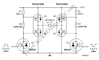
This is a driver circuit for siren. This circuit usually used for car alarms. To build this circuit, we use VD-MOS FETs. This circuit receives 12 v supply from battery. A microprocessor sends complementary pulse waveforms to the driver circuit as inputs. Here is the circuit :
This circuit uses two PHC21025 which each of them contains two FETs. Two BSN20 VD-MOS FETs in small SOT23 packages also used in this circuit. The maximum configuration of this circuit needs eight components and the minimum configuration of this circuit needs six components
This circuit uses two PHC21025 which each of them contains two FETs. Two BSN20 VD-MOS FETs in small SOT23 packages also used in this circuit. The maximum configuration of this circuit needs eight components and the minimum configuration of this circuit needs six components
Magnetic Reed Switch Alarm
This circuit is made to be an alarm, both for home and handbags. If it is installed for home it will placed on door or windows, and if it is installed for bags or handbags it will placed in the bag. This circuit consists of a small magnet and a reed switch. If the magnet looses its contact with the reed switch, SW1 opens, the circuit starts oscillating and the loudspeaker emits a loud alarm sound.so this circuit suitable for use as an anti-theft alarm.
This circuit uses A complementary transistor-pair which is wired as a high efficiency oscillator, directly driving a small loudspeaker. Low part-count and 3V battery supply enable a very compact construction.
Notes :
The loudspeaker’s dimensions are limited only by the box that contain it.
An on-off switch is unnecessary because the stand-by current drawing is less than 20µA.
Current consumption when the alarm is sounding is about 100mA.
If the circuit is used as anti-bag-snatching, SW1 can be replaced by a 3.5mm mono Jack socket and the magnet by a 3.5mm.
Do not supply this circuit with voltages exceeding 4.5V: it will not work and Q2 could be damaged.
Audio Speech Compressor
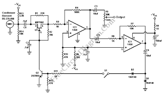
There are many low power SSB rigs and kits don’t have any real speech processor circuitry, although there is a built in speech processor in most modern HF. Speech processing is an important thing, when the SSB is operated at low power to get through the QRM. Speech processing can be done by this circuit. This is a simple and low cost circuit but it can perform well. This circuit includes the microphone element. So, we can assemble complete speech processor microphone in an old defunct desk mike. Here is the schematic diagram of this circuit :
This circuit contains a feedback amplifier and an audio preamplifier. S1 should be closed, to use the speech processor. R5 is used as the gain control for basic preamplified microphone that is given by Leaving S1 open. Q2 is triggered to conduct by voice peaks from the feedback amplifier, when S1 is closed. It causing the gate of Q1 to become negative. The resistance between the source and drain of Q1 substantially increase due to the gate of Q1 become negative. During very large voice peaks, Resistor R1 allows a small amount of audio to pass. to smooth out the voice, this circuit uses capacitor C2. C6 gives a time delay, so we can do the fast attack, slow release action. R7 can be replaced by a potentiometer. So we have variable speech compression control. [Source: Radio Amateur Society of Norwich]
This circuit contains a feedback amplifier and an audio preamplifier. S1 should be closed, to use the speech processor. R5 is used as the gain control for basic preamplified microphone that is given by Leaving S1 open. Q2 is triggered to conduct by voice peaks from the feedback amplifier, when S1 is closed. It causing the gate of Q1 to become negative. The resistance between the source and drain of Q1 substantially increase due to the gate of Q1 become negative. During very large voice peaks, Resistor R1 allows a small amount of audio to pass. to smooth out the voice, this circuit uses capacitor C2. C6 gives a time delay, so we can do the fast attack, slow release action. R7 can be replaced by a potentiometer. So we have variable speech compression control. [Source: Radio Amateur Society of Norwich]
Random Blinking (Flashing) LED
We can using this circuit to make the LEDs blink in a random pattern according to the slight differences in the three Schmitt Trigger oscillators.
The CD4511 is BCD to 7 segment Driver, so the pattern of the led is actually the come from seven segment representation. Arrange the LEDs to be far from seven segment pattern if you want to avoid people analyze your circuit. The randomness is based on the frequency difference because the 22uF and 47k resistors that determine the frequency have at least 5% tolerance.
Subscribe to:
Posts (Atom)


