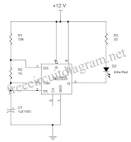
There are pictures on the IC1 NE555 is the cable as astable multivibrator increase IR diode D1 to emit IR pulses. That operates at a frequency transmitter must be set 120Hz.The IR pulses transmitted by D1 will be reflected on the obstacles and received by D2 (infra red). You can also use the photo diode. The received signal amplified by akan IC2a.The peak amplified signal is detected by diode D4 and capacitor C4.R5 and R6 compensates the forward voltage drop of D4.The output voltage from the peak detector will be proportional to the distance between the bumper cars and obstacles. Output from the peak detector is given to the input from three other comparators IC2b, IC2c and IC2d the IC2 LM324. The comparators switch status LEDs according to their input voltage inverting input and the reference voltage at the non-inverting input. Resistances R7 to R10 is used to set the reference voltage for the comparators. Here is a circuit diagram for the image of the recipient:

To note that the D1 & D2 must be installed near (~ 2cm) of each other, seen in the same direction. D1 which can be a general purpose IR LED. D2 which can be general purpose IR photo diode with filter Sunday. Right to work in the circuit, some trial and error is required with the position of D1 and D2 in the dash board. All capacitors must be rated 25V.

No comments:
Post a Comment